Jet3D Tutorial 2
Advanced fetures of Jet3D's level designer - jDesigner3D or jDesignerClassic11
Overview: This tutorial will show you some of the more advanced features of the Jet3D level editor. If you have not already visited the first tutorial on geometry construction, you should complete that before going on . This tutorial will not cover level construction. In this tutorial we will take you through the steps of populating your worlds with actors and particle systems, attaching controllers to those actors and particle systems, and we will touch upon using portals in Jet3D. This is a lengthy tutorial so you may want to set aside a little time to tackle this one. Before we get started on this tutorial, please note that cut brushes are now represented by white and solid brushes are represented with orange. This is reversed from Tutorial 1 and will remain as is for future versions.
|
Getting Started:
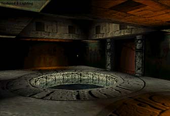 Let's begin by loading our barren Mayan level. Click File|Open then choose tutorial2.j3d.
If at any time you want to see the completed file, you can open tutorial2_complete.j3d
to view what the final version looks like. I have already created an ancient
Mayan temple for you that we will populate with actors, particles systems,
dynamic lights, portals, and any other cool features that are continually
being packed into JEdit 2.0. I have also already placed the lighting except
for a few dynamic lights that we will place to make some fire! We want to
make this room come alive with sound and movement. First I want to drop
down a few actors and get some props and some movement going on in this
room.
Let's begin by loading our barren Mayan level. Click File|Open then choose tutorial2.j3d.
If at any time you want to see the completed file, you can open tutorial2_complete.j3d
to view what the final version looks like. I have already created an ancient
Mayan temple for you that we will populate with actors, particles systems,
dynamic lights, portals, and any other cool features that are continually
being packed into JEdit 2.0. I have also already placed the lighting except
for a few dynamic lights that we will place to make some fire! We want to
make this room come alive with sound and movement. First I want to drop
down a few actors and get some props and some movement going on in this
room.
Step 1:Adding an Actor with Motion
 First we want to drop an actor object into the scene so that we can choose the actor that we want to work with. Make sure that Actor is selected from the object list box, then click on Object and you are ready to place an actor object.
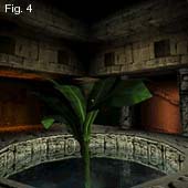
 We want to place a plant in the middle of the circular water well. In the top orthogonal view, place the actor object in the center of the cylinder. We'll place the height position once we've told the object what actor it wants to be. Upon placing the object, the right hand dialog will pop up with the actor properties. The dialog will appear like Fig. 2. A brief description of the dialog properties:
| Name | Actor Name |
| Position | This is the x,y, and z coordinates of the actor. This dialog will drop down for manual entry. |
| Scale | Relative Scale of the actor |
| Ambient | This is the ambient color of the object. Choosing a good ambient will help to blend your actor into the environment. I generally like to keep the ambient dark and pick up a slight amount of surrounding texture color to simulate bounced light. Choose from a color picker or manual RGB input. |
| Fill | The fill light will be a more dominant light on the character. In this particular case, we have a light filtering in from above our plant, so we want to pick up the color of the light cascading down and light our plant from the top. You will also find settings under the fill light to move the angle of the fill light. See Fig. 3 Choose from a color picker or manual RGB input. |
| Collision Box | You may turn the collision box visibility on and off and tweak the collision box size for collision testing |
| Render Box | You may tweak the render box size as well. The render box tests whether or not the camera can see the object or not. Any object not seen is not rendered. |
| Per Bone Lighting | Per Bone Lighting allows for more precise lighting across an actor as opposed to one centralized root bone. |
| Use ambient light from floor | Picks up lighting from the light maps on floor. |
| D Lights | Number of dynamic lights that can act upon an actor at any one time. |
| MT Scale | Motion Scale determines the playback speed of an actor. Default is set to 1 or the exact speed of the actor animation. A value of .5 would be half as fast and so on. |
| Actor | Pulldown list lets you choose from any actor contained in the actor directory |
| Motion | Motion that you want to use which is stored in the .act file. |
| LBone | Specifies a particular bone as the target for the fill light. Drop down dialog box lists all bones in the actor to choose from. |
 Fig. 3 shows the basic fill light dialog. To use the fill light, choose the color that you want to fill the actor with then use the X Deg, Y Deg, and Z Deg to shift the fill light around to the position that you want it. You will be able to see the fill light move in real time so that you can place your actor lighting precisely. FN Actor Relative will keep the fill light relative to the actor, if it is checked off then your fill light will move as the actor turns and changes direction.
 Now that I've described all of the functions in the dialog, you will want to make sure that your actor is selected then fill the properties as I have entered in Fig.2 and Fig 3. First select your actor from the actor list box and choose plant.act. Once the plant.act is loaded then you'll choose plant01 in the motion listbox. Any motion contained in the actor file will show up in this list box. The ambient value is a dark grey (36,36,36) to give the plant some illumination from light that would bounce from the floor to light the bottom of the plant. Since I have a dominant light source coming directly from the top, I want my plant lit from the top so I chose the yellow fill light ( 255, 255, 128) with it's FN (fill normal) at 0,0,0 or shooting straight down. D Lights I left at default 3 and MT Scale can be anywhere from 1 down to .5. If you want the the plant to sway slower, use a value of .5 which works really well.
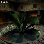 We should now have our first actor with a motion assigned to that actor. To actually view the animated motions, you will need to turn on the Animate button next to the Object Listbox. If you want, you can duplicate this actor for a fuller foliage effect. Experiment with Scale and MT Scale set to slightly different values so that the motions get out of sync giving a truly random feel to the swaying. Everything else should stay the same. You might give the second plant a slightly different rotation by using the Mode >> Rotate/Shear command. Fig. 5 is one example of what adding the second plant would look like. It looks much fuller and believable.
Step 2: Adding Ambient Sounds
 Alright, what's wrong with this picture? Sounds... there are always crickets and frogs hanging around in these deep, dark secluded Mayan ruins. Lets add some sounds shall we? You will want to make sure that you select AmbObject from the Objects listbox. To add the object, click the object
  button and you are ready to place the sound. (Fig. 6) I have chosen to put the frogs in a dark corner of the room. As soon as you lay the object down, the right hand dialog box will give you the appropriate options for you to choose from. AmbObjects are pretty straight forward. In the FileName listbox, scroll down until you find amb_frogs.wav and select it (Fig. 7). Change the Radius from the default of 1000 down to 200. Your should be hearing around frogs singing away in it's dark little corner. Run around through the level and you will be able to see how the radius function of the sound works. The sound will fade out the further you do away from the source. Just for fun, add another sound on your own, anywhere within the room. I chose to place a cricket sound in the opposite corner using the cricket00.wav. You can play with the radius to
 get it where you want it. This sound is another filler object that keeps the frog sound from being to over-powering and reduce the repetitive nature of the frog sound by blending with a second sound that is not synced with the first. This is just my own approach at making an immersive environment.
Step 3: Adding an actor and attaching a path to the actor
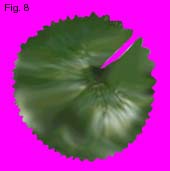 Our water well just will not complete until we have a water lily floating around slowly on the surface of thewater. I created a special texture with the hot pink color in the 255palette position which is reserved forthe transparent color. This texture was applied to an actor for us to drop down on the surface of the water.
We want to select Actor again from the object button listbox and place an actor object in the water well off to the side away from our plants. We want this actor to float around so we are going to need to attach a PathObject so that we can keyframe our movement. From the Object button listbox, choose PathObject then select the Objectbutton to place the entity in your level. The position of the PathObject is irrelevant and will not show up as anactual object in the scene.  Once you placeyour PathObject, the right hand dialog will give youthe option to Add Position Time Line or Add Property Time Line (see. Fig. 10). Since we want this lily tomove around slowly, we want to add a Position Time Line. Clicking on Add Position Time Line will reveal a keyframingtime line as well as extra options to chose from (see Fig. 11). In theObject Listbox (Fig. 11), we want to choose Actor3 so that we hook the time line to the lily that we just created.
Now that we have the PathObject hooked to the lily pad, we can begin animating our path. In the timeline, we want to set keys at the 0 position in the timeline. JEdit 2.0 gives you 3 options in creatingkeys. Clicking on the ![]() Pos line will set a key on the Position track, clicking on the Rot line will create a rotation key on the rotation track, or you can click on the Rot&Pos line and you willlock both a Position and Rotation key at the current spot. Let's make a few more keys. The timeline is designated in seconds and we want the movement to be slow.
Pos line will set a key on the Position track, clicking on the Rot line will create a rotation key on the rotation track, or you can click on the Rot&Pos line and you willlock both a Position and Rotation key at the current spot. Let's make a few more keys. The timeline is designated in seconds and we want the movement to be slow.
 Since we want the lily to move slowly, we'll make the full looping segment to be approximately 40 seconds long. After setting keys at the 0 position, let's move our actor closer to the plant that we've inserted. After moving our actor, we want to now set keys in the Pos&Rot track to lock that movement into a keyframe. To check your progress, you can grab the slider (red selected bar in Fig. 13) and run it back and forth or hit play. Our third step is to bring the lily back to the original starting place so that it loops continually. We can achieve this two different ways. (A) We can select the keys at time 0 which will bring the lily back to the starting point then set a key in the Pos&Rot track at time 40.0 or (B) we can select the keys at time 0.0, hold down shift and drag the newly created keys to the position we want. Either way will work fine. For a seamlessly looping animation you will always want to copy the beginning keys
  to the final frame. For our final step (step 4) we want to test to make sure that we can in fact set a Rotation key by itself. Set a key somewhere around time 10.0 in the the Rot track only. Select the key. Once selected, the key turns red meaning that you can now edit this key. Use the Rotation tool (>>Mode>Rotate/Shear) and rotate your actor from the top down view approximately 90 degrees in any direction. This will now make your lily pad rotate between the 0.0 and 20.0 time period. Our lily pad now moves and rotates on a very simple path. The final thing that we need to do is to select the details rollout and choose Loop Time which will start the animation over after hitting the last keyframe (Fig. 14).
Tip: If you ever select another object before you are finished editing the PathObject, you'll need to reselect the PathObject from the List menu on the left hand dialog box. Everything in the editor can be selected from this dialog. Since PathObjects don't actually drop a physical object in the editor, you will need to retrieve it from here.
Step 4: More Actors
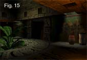 Step 3 was a long tutorial so for this step we just want to throw in a couple of actors, in this case being some Mayan pottery just for some decoration. This is a simple exercise to try on your own and to get your scene to look like the scene to the right (Fig. 15). You will need to place the actor, work on the scale, and try your hand at the ambient and fill lights to blend your actors into the scene. You will also want to evaluate where your light source is compared to the location of your pottery so that you can accurately place the angle of the Fill Light Normal (FN). Let's use pot01 and pot02 for our actors.
Step 5: For all you pyros out there, let's make some FIRE!
 I will start with placing a dynamic light in the lower left hand corner of the Fire Temple as in Fig. 16. Once we have the dynamic light set, we want to set the color, radius, and brightness. Make the color of the dynamic light an orange hue, 255, 128, 0. A radius of 180 and brightness of 5 (Fig. 17) works pretty well. You can vary the hotspot that the light will give you by tinkering with the brightness value. A brightness value of 5 generates a large saturated hotspot where a value of .5 would create a soft light but a larger radius is needed in order to light the same amount of area. You will want to position the light so that you get a nice gradation across all surfaces. Experiment to find the best position.
Now let's get this light to flicker. A roaring fire would produce a fast flicker. This will take a lot of  experimentation to accurately produce the most realistic effect. To make your dynamic light come to light, we need to add another path controller that will hook onto the dynamic light. Choose the Pathbject from the Object List box. This time when we add the timeline we want to choose the Property Time Line (Fig. 10) instead of the Path Time Line that we used on the lily. Selecting the Add Property Time Line will pull up Fig. 18. On the Object ListBox, choose the Dynamic Light1 and in the Property Listbox, we'll want to animate the radius property. As you can see, you can set your objects up so that any property can be animated with a PathObject. Once we choose radius, we are given a timeline that will allow us to enter keys to animate the radius just as we did on the PathController for the water lily. To get the flicker, we are going to add 7 keys in
  between time 0.0 and 1.3 so you may want to zoom in on your timeline so that you can easily set the keys. After laying the 7 keys, one on 0.0, one on 1.3, and 5 in between at random time slots, we can then begin selecting each key and changing the radius value for each. Key in the values for each key with the values that I have typed in over the key. You will change the value in the Value slot on the right hand side properties dialog.
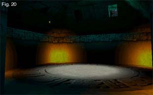
The final thing that you will need to do is to open up the details dialog as we did with the lily and set the animation on an endless loop (Fig. 19). You can now view your work by hitting the Play button on the Time Line  Dialog Box and you'll also need to make sure that the Animate button is on as well.
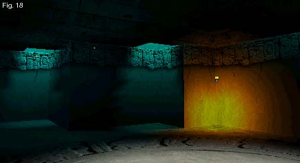
Now that you've created a flickering dynamic light, duplicate this procedure for the other four corners of the Temple of Fire. Once you finish, you'll have a room full of dancing light that should something like Fig. 20:
Step 6: Using Particle Systems to Start the Fire
 Alright, now that we have some dancing lights, we can throw in the main attraction...the flame and smoke. To create this effect we will haveseparate artwork for the flame and the smoke. Also, if we study a flame you'll find a fast roaring flame but a slower paced billowing smoke which will require
  to separate particle systems to create the effect that we want.
To begin, we want to use the Object Spout from the Object Listbox. We want to place the spout in approximately the same spot as the dynamic light but closer to the floor to create the actual flame. For the flame, choose flame03.bmp for the Bitmap and a_flame.bmp for the alpha channel of the flame in the Art dialog box (Fig. 21). Use the values in Fig. 21 for the flame properties. Below is a description of the properties:
Note: The Highest properties need to be set first. If you try to change SpeedL to 40 for instance, and SpeedH is set to 20...your input will not be accepted. This applies to Speed, Scale, and Life.
Now that we have fire...we need smoke. Since our smoke contains some crystalline particles, our smoke should pick up color from it's surrounding environment. This environment calls for an orangish glow from the bottom and a pale blue from the opening in the ceiling. A gradient map with an smoke alpha map will create the effect that we're looking for.
| Rate | 0.25 | Rate at which a particle is spawned (1 every .25 seconds) |
| Angle | 0.1 | Spread Angle of the particle system (choose .1 for the flame because we want to keep the flame tightly confined) |
| SpeedL | 40 | Lowest Speed a particle will travel (measured in units per second) |
| SpeedH | 60 | Highest Speed a particle will travel (measured in units per second) |
| ScaleL | 2 | Lowest Scale a particle will be spawned at |
| ScaleH | 3 | Highest Scale a particle will be spawned at |
| LifeL | 1 | Minimum amount of time a particle will exist |
| LifeH | 2 | Maximum amount of time a particle will exist (Flame should die quickly) |
| MinColor | default | Leave as white because we will pick up the color from the artwork |
| MaxColor | default | Leave as while because we will pick up the color from the artwork |
 To create our smoke, let's drop down another Spout object on top of the flame spout. This time we want to pull the smoke spout a few units above the flame since the smoke will originate further above the flame, this will be easier to tweak when we get the smoke displaying in real time. To select the artwork, this time you will need to select 64 instead of 32. Our maps smoke.bmp and a_lvsmoke.bmp or both 64x64 maps.
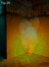
 Use the properties in Fig. 22 to create our smoke effect. We will set the rate to 0.5 since we want the smoke to spawn at a slower rate than that of the flame. The angle is set to 0.6 because we want the smoke to fan out as it rises. SpeedL & SpeedH are set much lower than the flame however the Minimum and Maximum life of the smoke lasts much longer. The completed fire effect should look similar to Fig. 23
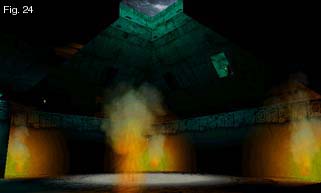
Try the other three corners for yourself. Try varying the numbers slightly so that you get a randomized effect among the four flames. The end result should look something like Fig. 24:

To finish off our fire effect, let's add in an AmbObject and assign a crackling fire sound to each of these torches for a little ambient background noise. Place one in each corner using torch.wav and a radius of approximately 200 units.
Step 7: Adding Portals
 Now that we have most of the inside of our Mayan temple complete, let's set this temple deep in the rain forests of South America. I have constructed a jungle that you will use as your skybox. We need to place askybox portal inside of this then set a couple of our faces to point to the portal. Why do we want to use a use a skybox portal? Currently we have a jungle texture on the faces on the openings now, but these textures do not give us a sense of depth to the jungle. By using a skybox portal, the jungle will be projected out away from the opening giving us the feeling that we are truly in a jungle and we will see different angles of our jungle as we move our point of view around.
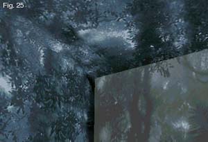
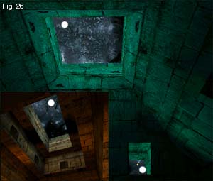 Fig. 25 is the pre-made jungle scene that we will use to set our skybox portal into. Fig. 26 displays the three faces that we will set to look at our jungle. To begin, select Portal from the Object Listbox. Once you've chose Portal, click on the object button and drop a portal in the middle of our jungle skybox located just to the right of our Fire Temple (Fig. 27). Once you've dropped your portal and positioned it in the middle of the box, you will need to select Skybox in the properties menu (Fig. 28).
 Now that we have our portal placed in the scene, we can go back and actually associate a few faces to point at these portals. We will want to change the three faces which are openings to the jungle as marked in Fig. 26. In order to associate the face, we need to select the face and open up the Face Info dialog
  for each face. Under the Portal Listbox, we want to select Portal1 which is the name of the portal that we just placed in our jungle. We also want to select the Invisible flag. This will assure that no artifacts from that face draws at all. Once you've completed this step, move your camera around the scene looking up at the portal to see what the skybox portal does for your scene.
 Tip: Selecting Transparent with a 0 Alpha is not the same as Invisible. If your face is set to Transparent and 0, the engine will still check each pixel to determine if it needs to draw. Setting the Invisible flag can help performance in this case because the engine does not need to check those pixels ever.
The skybox is only one use of portals. Portals can be used for other things such as rear-view mirrors, security cameras, transporters, and many other uses. Let's create a portal that is not a skybox. We'll set a camera to look at a scene and project that scene onto a face as we did for the jungle. Many people don't realize that the Mayan's could summon portals to anywhere they wanted to travel. We want to visit the Great Pyramids so let us open up a portal on the floor of the Fire Temple so that we can see what's going on over there. I have added an opening on the floor for us to attach to another portal that will look at the Pyramids.
The actual Portal object has already been placed. You can view the properties of the portal by going to the List Tab on the left hand side, maximizing Portals, and selecting Portal 2. You will see that they only difference between this portal and the one we created for the jungle is that the jungle had skybox selected and this particular portal does not. We just want to look from the point of view of the camera for this portal.
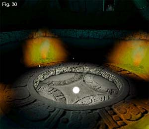
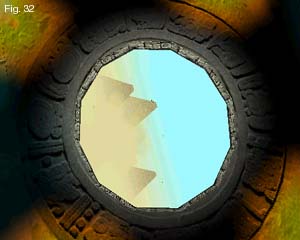
Select the Face designated in Fig. 30, open the Face Info dialog and select Portal2 from the Portal Listbox. Again, we want to check the Invisible flag and uncheck Transparent. Your configuration should look like Fig. 31. Once this is done, you should be able to see the Great Pyramids in the middle of a sand storm (Fig. 32). This completes adding portals to the tutorials. You should be able to see that this is a very powerful feature that is new to the Jet3D environment and can be used in many ways for many interesting effects.
Tip: If you want to get wild and crazy, you can animate the portal inside of the Pyramid room to simulate earthquakes or otherworldly phenomenon!
Step 8: Adding Models
 We're getting close to the end. We want to be able to add models to our scene for items such as doors, swinging platforms, and other world geometry that we want to animate and perform special functions upon such as triggering events. Models are world geometry objects that we group into special groups that contain all of the pieces for that particular model. This could be a double swinging door with a trigger that spins a handle which causes both of the doors to swing open and a 100 ton stone ball comes rolling down the corridor to smash you like a grape. Let's begin our model by navigating to the Lists dialog on the Left Hand Side (Fig. 33). The default should by pointing to Type and we want to select Model. You will see that everything is currently grouped into Default0. We want to add a door into our scene coming into the Fire Temple so we want to choose Add Model from the Lists dialog box. When we select the Add Model button, you will be presented with a dialog box to create a new Group (Fig. 34). Give the group the name 'Door'. This creates a new group called Door (Fig. 35).
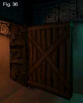
 Let's create a brush for our door and put a texture to it. Once we've created our brush and lined up the textures correctly (Fig. 36 & 37), we will want to shift that brush into our newly created group 'Door'. We can do this by selecting the brush (highlighted if selected) from the Lists dialog box (Fig. 33) and dragging the highlighted brush name and dropping it into the group 'Door' (Fig. 35). Your model is now in a group all to itself. If you would like to create multiple brushes into this group, set your Current group to 'Door' and begin creating objects. This can help you keep your scenes
  organized room to room or however you choose to organize your objects. The model that you created can now be animated if you like. We will explore models more in depth at a later date
Step 9: Camera Flythroughs
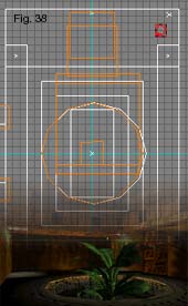 The final thing that we need to cover is doing a camera flythrough and cutscenes for the level that we just made. To do this, we want to go ahead and add an extra camera to our scene using the Camera object. Place a camera in the upper right hand corner of the first room such as Fig. 38.
We can add a PathObject Controller to our camera the same as any other object in the scene. Choose Object>PathObject and drop a controller into your scene. Again, let's choose the Position Time Line (Fig. 10) and hook the controller to the camera you just created. Once you've hooked the camera to the controller, a Position/Rotation Timeline appears in front of you and you are ready to animte. To animate your camera, you can either drag your camera in the ortho views and then set a PosRot key or you can navigate in the 3D view to where you want and set a PosRot key at the time that you want. You'll want to experimentwith creating, moving, and deleting keys from the timeline. Fig. 39 is the approximate layout ![]() of the final path that I have created. You can recreate this path or create your own. The different coloring designates cuts in the path.
of the final path that I have created. You can recreate this path or create your own. The different coloring designates cuts in the path.
In order to create a cut scene, we need to use a special key. When you get to the point that you want to jump to an entirely different position, line up your camera on the ending position of your current path and select 'Insert Cut' located on the timeline. This will lock your current camera position as the final key on the path. You will see a key such as Fig. 41, which is a double sided key. To move to your new position, select the right hand side of the 'Cut' key. When selected, the key will turn red (animatable) just as Fig. 41. For the first key you will want to physically move your camera into position using the ortho views instead of the 3D view to position your camera. This new position will be the jump-to position for your new cut scene. After setting that first 'Jump-to' position, you can animate using the 3D view again and setting keys where you need them. To view your camera path, hit the Play key and make sure that Animate is on. Instant fly-thru.
This concludes the advanced animation tutorial. I have briefly touched on the new features added since the geometry construction tutorial. You can get much more in depth and add multiple controllers to single objects. You can hook particle systems to path controllers and spray particles all around if you like. Just about anything and everything is animatable...GO CRAZY WITH IT! ENJOY.